A static equipment foundation is a structure, often made of reinforced concrete, designed to support non-moving industrial equipment like pressure vessels, tanks, and heat exchangers. This blog walks through the journey from concept to construction-ready documentation, highlighting how digital tools like Autodesk Revit transformed the process.
Structure Type
Equipment foundations for static equipment such as pressure vessels, heat exchangers, storage tanks, columns, reactors, etc.
Scope of Work
-
Structural analysis and design of equipment foundation
-
3D modelling of the foundation
-
Preparation of structural drawings and bar bending schedule
Design Challenges
Precision Requirements
Static equipment demands tight tolerances for anchor bolt placement and baseplate leveling. Achieving this in a congested rebar environment was a key challenge.
Rebar Congestion
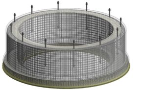
The pedestal had high reinforcement density due to seismic and wind load requirements. Coordinating rebar with embedded items required meticulous detailing.
Interdisciplinary Coordination
Mechanical and electrical systems introduced embedded conduits, and equipment had to be integrated without compromising structural integrity.
Constructability
The foundation design had to be practical for site execution, with clear bar bending schedules and minimal rework.
Design Factors
-
Equipment properties: The foundation’s design is heavily influenced by the equipment’s weight, dimensions, and shape.
-
Operational loads: Must account for the equipment’s weight, as well as forces from internal pressure, external loads, thermal expansion, and potentially seismic activity.
-
Soil conditions: The type of soil and its bearing capacity determine the foundation’s size and depth.
-
Presence of nearby structures: Presence of nearby structures is another factor which determines the size of the foundation.

Engineering Strategy
Structural Design
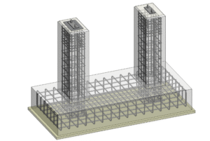
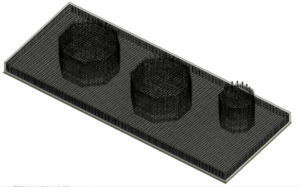
The type of equipment and shape of foundation required was identified. Isolated footing was provided for foundation with light to moderate loads with good soiling conditions and combined footings or raft when equipment is closely spaced or soil bearing is low. Loads and load combinations were analyzed as per Euro code and Algerian code. The foundation was designed to ensure stability, minimize settlement and loss of contact, and resist bending moments, shear forces, and crack width.
3D Modeling in Revit
The entire foundation including pedestal, anchor bolts, and rebar was modeled in Revit. This enabled real-time clash detection and seamless coordination with other disciplines.
Rebar Detailing
Revit’s rebar tools allowed us to visualize bar placement, optimize lap lengths, and ensure clear cover compliance. Hooks, bends, and splices were modeled accurately for fabrication and to prevent clashes with anchor bolts.
Documentation
Construction drawings and BBS were extracted directly from the Revit model, reducing manual errors and improving site efficiency.
Conclusion
This project showcased the power of integrated design and digital modeling. By combining structural engineering with BIM tools like Revit, we delivered a foundation that was not only structurally sound but also construction-ready and coordination-friendly.
About the Author
Maya K S is an experienced structural engineer with a strong background in structural design, analysis, and project management across a range of complex structures. She specializes in applying sound engineering principles to achieve safe, functional, and cost-effective solutions. Her professional experience includes working on refinery and power plant structures, where she has demonstrated proficiency in structural analysis software, construction methodologies, and project coordination. Combining technical expertise with practical insight, she consistently delivers efficient and reliable engineering outcomes.