The project involved designing a steel pipe rack / pipe bridge for an oil and gas plant. This rack serves as the backbone for routing multiple process pipelines, cable trays, coolers, and equipment platforms. The structure had to ensure safe operation, optimized material usage, and future flexibility, while accommodating maintenance access and equipment clearances.
This blog highlights the design approach, obstacles, and resolutions involved in creating this complex structure.
Project Overview
Structure Type:
Multi-bay steel framing system with rolled and built-up sections.
Scope of Work
-
Analysis and Design:
Global structural analysis and design of both superstructure and foundation using advanced software, considering seismic response spectrum and wind actions. -
Connection Design:
Structural connections, including base plates and member-to-member joints, were meticulously designed to ensure the safe and efficient transfer of forces. -
Modelling:
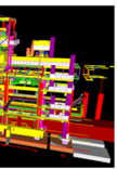
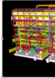
Creation of a 3D structural model coordinated with piping and equipment layouts. -
Drawings:
Preparation of detailed structural drawings.
Primary Challenge
The main challenge was to design a safe yet optimized structure capable of withstanding high seismic and wind forces, while supporting multiple pipes and equipment without excessive material usage.
Design Challenges
Seismic and Wind Effects
-
High lateral forces demanded stringent drift control and ductile detailing.
-
Wind-induced sway and uplift required strong anchorage and bracing.
Load Complexity
-
Multiple pipe sizes, coolers, and trays created eccentric loads and torsional effects.
-
Future load provisions added uncertainty to the design.
Optimization vs Safety
-
Balancing material economy with structural strength under extreme load combinations.
Foundation Design
-
Uplift and overturning moments under seismic and wind combinations.
-
Settlement control to maintain piping alignment.
Constructability and Access
-
Dense piping and equipment required clear walkways and safe margins.
Engineering Strategy & Structural Design
Structural System Selection
-
Adoption of a robust yet efficient framing system to carry gravity loads and resist lateral forces.
-
Combination of moment frames and braced frames to ensure stability while minimizing interference with piping and equipment layouts.
-
Provision of expansion bays to accommodate thermal movements and future modifications.
Load Identification & Distribution
Consideration of all relevant loads:
-
Permanent loads (self-weight, grating, equipment)
-
Variable loads (maintenance live load, pipe operating and test loads)
-
Environmental loads (wind and seismic forces)
Loads were distributed realistically, accounting for eccentricities from pipe clusters and equipment.
Analysis Approach
-
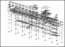
Development of a 3D structural model using advanced analysis software.
-
Global analysis for overall stability and local checks for individual members.
-
Inclusion of dynamic effects such as seismic response and wind-induced vibration.
Member Design
-
Beams, columns, and bracing designed for combined axial, bending, and shear forces.
-
Lateral stability ensured through adequate bracing and restraints.
-
Serviceability checks for deflection, drift, and vibration to ensure operational safety.
Connection Detailing
-
Connections designed to transfer forces effectively between members.
-
Ductility and strength ensured for reversible and cyclic loading conditions.
-
Simple, inspectable detailing adopted for ease of fabrication and maintenance.
Foundation Design
-
Foundations designed to resist vertical loads, lateral forces, and overturning moments.
-
Uplift and settlement control addressed to maintain alignment of piping and equipment.
-
Foundation type selection based on soil conditions and load intensity.
BIM Integration
-
BIM coordination used for clash detection between structural elements, piping, equipment, and foundations.
-
Enabled real-time interdisciplinary collaboration, improving constructability.
Safety & Access
-
Integration of walkways, guardrails, kick plates, and safe margins around openings.
-
Adequate space ensured for maintenance and future expansion.
Design Outcome Summary
-
Excellent structural stability achieved through anchor bays and braced frames.
-
Seismic and wind effects, lateral drift, and vibration maintained within safe limits.
-
Optimized material usage without compromising safety or reliability.
-
Expansion bays and future load provisions integrated into the design.
-
Clear walkways and access points ensured ease of construction and maintenance.
(3D model and wireframe view generated in STAAD for analysis)
Conclusion
This project demonstrates Paradigm’s capability to deliver strong, reliable infrastructure for the oil and gas industry under demanding conditions. By combining rigorous seismic and wind-resistant design principles with cost-effective engineering solutions and BIM-driven coordination, the steel pipe rack was designed to be safe, durable, and future-ready.
The final structure integrates seamlessly with plant operations and meets the evolving demands of modern industrial facilities.
About Author
Ashly Paul is an experienced structural engineer with 6+ years of experience in structural design, analysis, and management of diverse structural projects. She has worked on refinery and power plant structures, with a strong focus on innovative and sustainable design solutions. With expertise in structural analysis software, construction practices, and project coordination, she brings both technical knowledge and practical insight to every project.