Introduction
In a highly ambitious structural retrofit project, we were tasked with strengthening an existing 15-storey reinforced concrete building to support an additional 5 floors. This upgrade required not only rigorous engineering analysis but also a highly coordinated effort in producing detailed construction drawings that addressed new load paths, retrofitting strategies, and phased construction plans.
Location: Europe
Key Challenges
Of all the structural elements, foundation strengthening was the most challenging:
Limited Accessibility: The building was already operational, limiting intrusive excavation.
As-Built Inconsistencies: Old foundation drawings were incomplete, and several unknowns were only discovered through scanning and controlled excavation.
Load Increase: Supporting 5 extra floors meant re-evaluating bearing pressures and deepening or widening existing footings.
Adjacent Structures: The proximity of neighbouring buildings restricted methods like piling.
The existing foundations had irregular geometries, non-uniform footing depths, and partial data from old drawings. We had to represent overlapping old and new elements, micropile positions, pile caps, jacketing zones, and underpinning extents — all in a tight and congested layout.
Another major challenge was preparing drawings for drilling through existing slabs and creating new structural walls. The drawings needed to show not just the new wall dimensions, but also precise drilling locations, cutting details, and the connection between new and old concrete. In many cases, we included enlarged sectional views, dowel bar layouts, and phased execution notes to guide site teams on how to safely break, drill, and rebuild without affecting the surrounding structure.
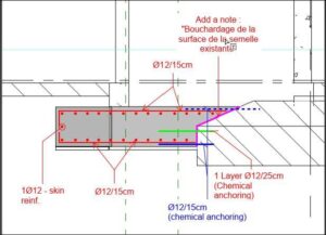
As part of the vertical expansion and structural upgrade, the design also included adding new slab projections (cantilevers or balcony extensions) to the existing floors. This added another layer of complexity to the detailing work. These projections had to be carefully integrated with the existing floor slabs, identifying the exact rebar layout in the existing slab to avoid cutting through critical reinforcement during anchoring.
Detailing the connection between new and old concrete, including dowel bar placement, epoxy bonding, and in some cases, additional steel brackets or angles.
Detailing Drawing Strategy
All existing elements were scanned using GPR and laser surveys.
Old column sizes, slab thicknesses, and beam depths were confirmed on-site before being integrated into the new GA and section drawings.
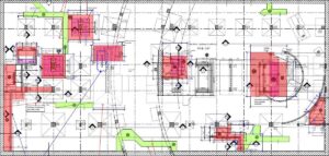
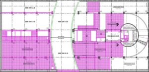
To distinguish between existing, to-be-demolished, and new elements, we used color-coding conventions across plans and sections.
This was especially important for floor plans showing new stiffening walls and enlarged columns.
Our detailing sheets weren’t just drawings — they were construction guides:
Phases clearly marked
Details of cut-and-extend beam methods and shear dowel placement
Site verification is everything – drawings are only as reliable as the data behind them.
Foundation work always needs room for redesign – keep contingency space in your drawings and plan notes.
Conclusion
Strengthening a 15-storey building and preparing it for an additional 5 floors isn’t just an engineering challenge — it’s a test of discipline, innovation, and teamwork. Every line drawn on a detailing sheet represented a decision shaped by structural demands, site constraints, and practical execution.
What made this project remarkable wasn’t just the complexity of the foundation or the scale of the retrofit — it was the synchronization of design intent with on-site reality. We weren’t just drawing reinforcements and extensions; we were crafting a blueprint for transformation, ensuring that the past and future of the building could coexist safely.
About the Author
Lalu M A has 23+ years of experience in the preparation of structural detailing drawings. Over the years, he has worked on a wide range of projects, including high-rise buildings, industrial structures, retrofitting works, and foundation strengthening.
He specializes in creating clear, accurate, and practical drawings that help engineers, architects, and contractors bring their designs to life. He understands the importance of connecting design intent with site realities, especially in complex projects like vertical extensions and structural strengthening.
With a strong focus on buildability, coordination, and site constraints, he has developed a reputation for producing drawings that not only meet technical standards but also support smooth execution on site.
This blog is based on real project experience and reflects the lessons learned from working closely with design and construction teams.
Related Services
Explore More Of Our Expertise: